Over my 30 years in this industry, I've seen countless projects get delayed or go over budget because of the wrong manufacturing choice. As a buyer or engineer, you're constantly looking for a process that delivers complex, small metal parts without the high costs of CNC machining1. This is where Metal Injection Molding2 (MIM) becomes a powerful tool in your supply chain.
MIM parts shrink significantly, about 15-20%, during the sintering process3. This is not a defect; it's a planned, highly controlled part of the manufacturing cycle. As an experienced MIM supplier, we leverage this phenomenon to achieve tight tolerances4, often as fine as ±0.3% of the dimension, making MIM ideal for intricate, high-volume components.
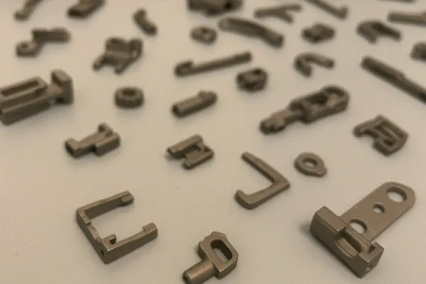
Understanding and mastering this shrinkage is the key to unlocking the power of MIM. It might seem like a risk, but it's a precise science that our team at Prime has perfected over three decades. Let's break down exactly how our ISO 9001:2015 certified process ensures we deliver perfect, repeatable parts to you every single time.
What causes shrinkage in MIM parts5?
Alarmed by how much MIM parts shrink? If you're used to subtractive manufacturing, the idea of a part shrinking 20% can sound unpredictable and risky. But the process is highly controlled, and the shrinkage is intentional.
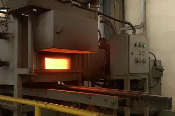
Shrinkage happens during sintering. The plastic and wax binder, which allows the metal powder to be molded, is completely burned away. This leaves microscopic gaps between the metal particles. High heat in our controlled-atmosphere furnaces fuses these particles, causing the part to shrink uniformly as it becomes fully dense metal.
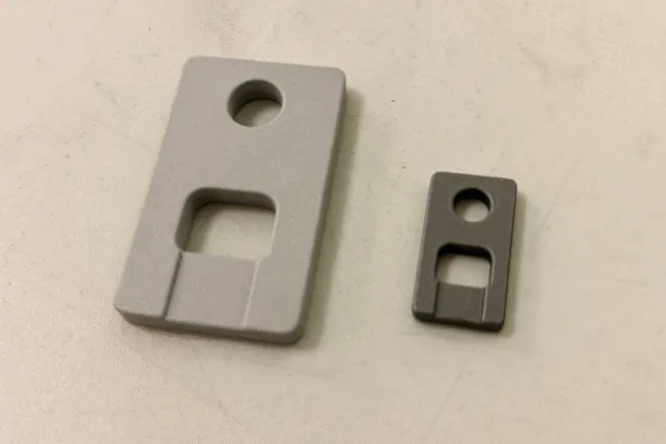
Let's dive deeper from a factory perspective. It all starts with the feedstock—a precise mixture of [fine metal powder](https://primefabworks.com/surface-treatment/)6 (typically < 20 microns) and our proprietary binder system. The entire process is governed by principles outlined in industry standards like the [MPIF Standard 35](https://www.3deo.co/manufacturing/new-powder-metal-alloys-added-to-mpif-standard-35/)7 for MIM Materials. This ensures that a part made today will have the exact same mechanical properties8 as a part made a year from now, a critical factor for any serious production program.
| Process Stage | Description | Key Change |
|---|---|---|
| 1. Green Part | The part as it comes out of the injection molding machine. | Shape is formed, contains binder. |
| 2. Brown Part | After the multi-stage debinding process. | Most binder is removed, part is porous and fragile. |
| 3. Sintered Part | After heating in our controlled atmosphere sintering furnace. | Pores are eliminated, part shrinks and densifies to 97-99%. |
How tight can tolerances be with MIM?
Are you concerned that MIM can't meet your strict tolerance requirements? You need precision, but the idea of shrinkage sounds like a gamble. It is not.
Typically, MIM can achieve as-sintered tolerances of ±0.3% to ±0.5% of a dimension. For a 10mm feature, that’s just ±0.03mm. Tighter tolerances are possible with secondary operations. Our commitment to these tolerances is validated through a rigorous [Production Part Approval Process (PPAP)](https://quality-one.com/ppap/)9 for every new part.
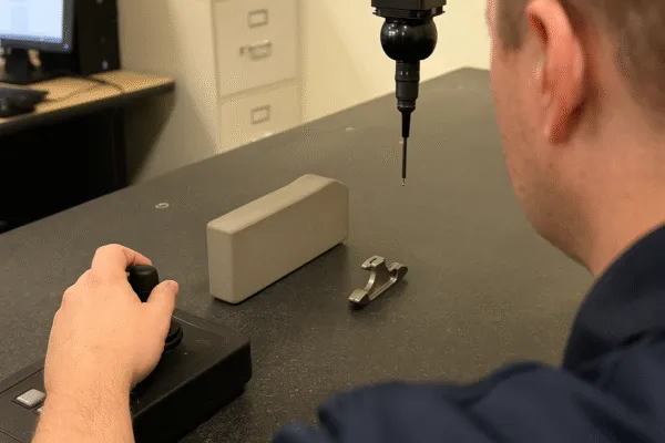
This is where experience truly matters. From a buyer's perspective, the last thing you want are delays from parts that don't fit. That's why our process starts with a collaborative Design for Manufacturability (DFM)10 review. My team works directly with your engineers to suggest minor tweaks that improve part consistency. This DFM is the first step in our formal PPAP submission. We build the mold using precise calculations based on the specific material's shrink rate, which we've validated over millions of parts. This proactive approach de-risks the entire project, ensuring the final parts meet spec without costly redesigns.
| Tolerance Type | Standard MIM Capability (As-Sintered) | With Secondary Operations |
|---|---|---|
| Linear Dimension | ±0.3% | < ±0.1% possible (Machining/Coining) |
| Hole Diameter | ±0.05 mm | ±0.01 mm possible (Drilling/Reaming) |
| Flatness | 0.005 mm per cm | 0.001 mm per cm possible (Lapping) |
When is MIM the best choice over other methods?
Are you confused about when to use MIM, CNC machining1, or casting? Choosing the wrong process can waste a lot of your time and budget. MIM has a clear sweet spot.
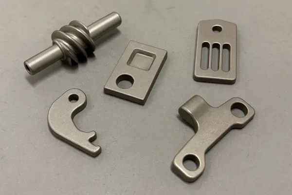
Choose MIM for high-volume production11, usually over 10,000 pieces per year, of small, complex metal parts. It's perfect when a part is too intricate for CNC to be cost-effective12 and needs better strength and surface finish than investment casting can provide. Explore our [Metal Injection Molding2 services to see more examples.
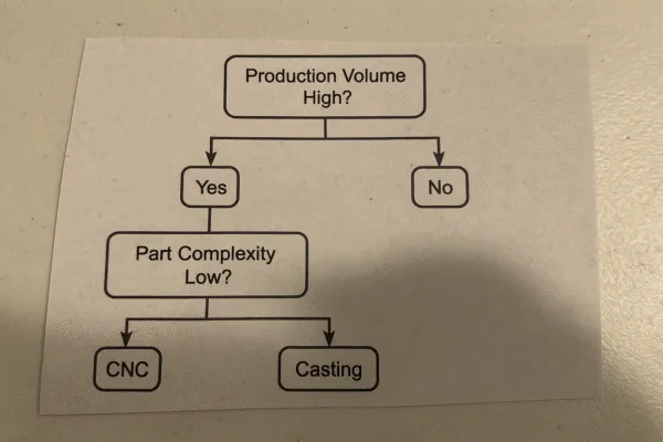
The key factors are complexity and quantity. The high upfront cost of a hardened steel MIM mold is quickly offset by the extremely low per-part price at high volumes. I once worked with a client, Kevin from the U.S., who was sourcing electronic components. His previous supplier's inconsistent quality caused major shipment delays. By switching to our controlled MIM process, he not only got better parts but also a reliable supply chain, allowing him to hit his sales targets. This is the real value of a trusted manufacturing partner.
| Cost Factor | Metal Injection Molding2 (MIM) | CNC Machining |
|---|---|---|
| Tooling Cost | High (one-time) | None |
| Material Usage | Very efficient (>98% utilization) | High scrap rate (material is cut away) |
| Labor Cost / Part | Very low (automated process13) | High (machine & operator time per part) |
| Ideal Quantity | 10,000+ per year | 1 - 1,000 |
How does material choice14 affect MIM shrinkage and tolerances?
Does your material choice14 complicate the MIM process? You might fear that picking a different metal will ruin your tolerances. It's a factor we manage every day.
Different metal powders create unique feedstocks, each with a specific shrink rate. For example, stainless steels like 17-4PH are highly predictable. We use our extensive material database to adjust mold designs and furnace profiles for each alloy, ensuring consistent, precise results.
This is where our expertise shines. We verify the chemistry and particle size distribution of every batch of incoming metal powder. From a buyer's standpoint, this means you can be confident that the material in your parts provides the exact properties your application demands, batch after batch15. We handle the science so you can focus on your product.
| Common MIM Material | Key Properties (Based on MPIF Standard 357) | Typical Applications |
|---|---|---|
| [17-4 PH Stainless Steel](https://www.upmet.com/sites/default/files/datasheets/17-4-ph.pdf)16 | High strength, good corrosion resistance. | Firearm components, medical tools, aerospace parts. |
| 316L Stainless Steel17 | Excellent corrosion resistance, biocompatible. | Watch cases, jewelry, surgical instruments. |
| Fe-2%Ni (FN02) | Good magnetic properties, moderate strength. | Automotive sensors, electronic housings, soft magnetic cores. |
| Titanium Alloys (Ti-6Al-4V)18 | High strength-to-weight ratio, biocompatible. | Medical implants, high-performance sporting goods. |
Conclusion
MIM is a powerful process for complex, high-volume metal parts. By mastering the science of shrinkage through deep experience and rigorous process control, we deliver precision and value, turning a manufacturing challenge into your competitive advantage.
FAQs about Metal Injection Molding2
What are the most common materials used in MIM?
The most common materials are stainless steels (17-4PH, 316L), low-alloy steels (FN02, FN08), and titanium alloys. As a specialized factory, we can also process materials like tungsten and copper alloys for specific applications.
How strong are MIM parts?
MIM parts are very strong, reaching 97-99% of wrought metal density. Their mechanical properties8 are far superior to die casting and are specified to meet industry standards like MPIF Standard 357. We can also perform post-sinter heat treatments to further increase strength.
What is the typical lead time for a MIM project?
A new project has two phases. Phase 1: Tooling & PPAP typically takes 6-8 weeks. This includes DFM, mold fabrication, and submitting initial samples with a full PPAP report for your approval. Phase 2: Mass Production begins only after your approval, with a typical lead time of 3-5 weeks.
What is the main difference between MIM and metal 3D printing?
The main differences are volume and cost. Metal 3D printing is ideal for prototypes and very low volumes, as it has no tooling cost. MIM is vastly more cost-effective12 for high-volume production11 (10,000+ pieces) where the low per-part cost justifies the initial tool investment.
Can you apply surface finishes19 to MIM parts?
Yes. MIM parts are fully dense metal and can be treated like machined parts. We frequently provide services like polishing, passivation, black oxide coating, and Physical Vapor Deposition (PVD) coatings, which add durability and specific aesthetic or functional properties.
What information do you need for a MIM quote?
For an accurate quote, please provide: a 3D CAD file (STEP/IGES), a 2D drawing showing dimensions, critical tolerances, and material callouts, and your estimated annual usage (EAU). This volume information is crucial for confirming that MIM is the right choice for you.
Ready to see if MIM is right for your project?
Upload Your RFQ or Contact Our Engineering Team Today
Compare CNC machining with MIM to see which method suits your project best. ↩
Explore the fundamentals of MIM to understand its advantages in manufacturing complex parts. ↩
Learn about the sintering process to grasp how MIM achieves its unique properties. ↩
Discover the techniques used to achieve precision tolerances in manufacturing processes. ↩
Learn about the factors influencing shrinkage in MIM to better manage expectations. ↩
Explore the role of fine metal powder in MIM and its impact on part quality. ↩
Discover how MPIF Standard 35 ensures quality and consistency in metal injection molding. ↩
Learn about the mechanical properties that make MIM parts suitable for various applications. ↩
Understand the importance of PPAP in ensuring quality and consistency in manufacturing. ↩
Learn how DFM can optimize your design for better manufacturing outcomes. ↩
Understand the advantages of high-volume production for cost efficiency and quality. ↩
Discover the key elements that contribute to cost-effective manufacturing solutions. ↩
Learn how automation can improve efficiency and reduce costs in manufacturing. ↩
Explore how selecting the right material can impact the quality and performance of parts. ↩
Understand the importance of consistency in manufacturing for quality assurance. ↩
Discover the unique properties of 17-4 PH Stainless Steel and its common uses. ↩
Learn why 316L Stainless Steel is favored for its corrosion resistance and biocompatibility. ↩
Explore the high-performance applications of Ti-6Al-4V in various industries. ↩
Understand the various surface finishing options available for enhancing MIM parts. ↩