
Designing powder metallurgy parts can be complex. A small mistake in the design phase can lead to major production issues, costing you time and money. Understanding key rules will help.
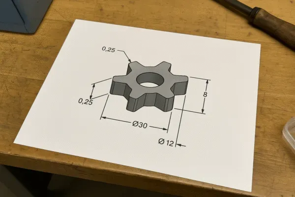
To design powder metallurgy parts effectively, focus on four core areas. First, select the right material density[^1] for strength. Second, specify achievable dimensional tolerances[^2]. Third, plan for the necessary surface finish[^3]. Finally, always design for manufacturability[^4] to control costs.
Transition Paragraph:
These four areas—density, tolerances, finishes, and manufacturability[^4]—are the pillars of a successful PM part. In my 30 years running Prime Fabworks, I've seen how mastering these fundamentals separates a successful project from a failed one. This isn't just theory; it's about avoiding costly tooling changes and production delays that I know buyers like you want to prevent.
How Does Density Impact PM Part Performance?
Your PM part needs to be strong. Choosing the wrong density can make it weak and unreliable, leading to failure. The right density ensures your part meets its performance requirements.
Density directly controls a PM part's strength, hardness, and ductility. Higher density means better mechanical properties but also higher costs. The key is to specify a density that meets your application's needs without over-engineering, balancing performance with budget.
Dive deeper Paragraph:
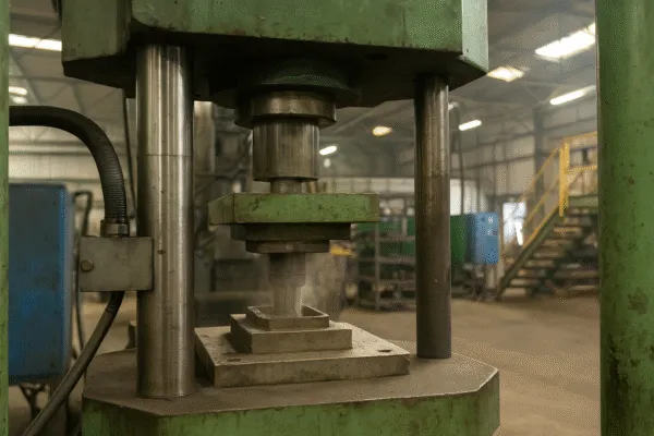
Density is the most fundamental property of a PM part. It's determined by compaction pressure and the sintering process[^5]. A lower density part has more internal porosity, which we can use for self-lubricating bearings. For structural components like the powder metallurgy parts we make, higher density is critical. To achieve this, we can use advanced techniques like double pressing/double sintering. The properties for various materials are documented by the Metal Powder Industries Federation (MPIF) in their Standard 35. These material behaviors are also extensively studied by organizations like ASM International, providing a deep well of data we use to ensure success.
| Density Range (g/cm³) | Porosity Level | Key Characteristics | Typical Application |
|---|---|---|---|
| 6.4 - 6.8 | High (15-20%) | Self-lubricating, lightweight | Bearings, filters, non-structural parts |
| 6.8 - 7.2 | Medium (10-15%) | Good balance of strength and cost | Gears, cams, medium-duty structural parts |
| > 7.2 (High Density) | Low (< 10%) | Excellent strength, hardness, wear resistance | High-stress gears, transmission components |
What Tolerances Are Realistic for Powder Metallurgy?
You need precise parts that fit perfectly. Unrealistic tolerances can make production impossible or extremely expensive. Understanding PM's capabilities helps you set achievable specifications from the start.
Realistic tolerances for PM parts depend on the compaction direction. Tolerances are tighter for dimensions perpendicular to the pressing direction (radial) than for those parallel to it (axial). Typical radial tolerances are around ±0.001 to ±0.002 inches per inch.
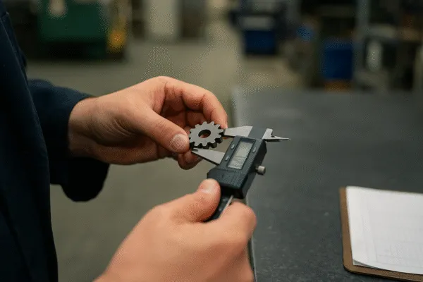
Dive deeper Paragraph: The PM process has unique traits that affect dimensional control. For every new part, especially for demanding industries, we complete a full Production Part Approval Process (PPAP). This isn't just a simple check; it involves creating control plans, FMEAs (Failure Mode and Effects Analysis), and providing first-article inspection reports to prove our process capability. This is how we, as an ISO 9001:2015 certified manufacturer, guarantee that our process can consistently hold your required tolerances. This comprehensive approach prevents surprises when the parts arrive at your facility.
| Feature Type | Standard (As-Sintered) | Precision (With Sizing/Coining) |
|---|---|---|
| Radial Dimensions (Diameter) | ±0.002 in/in | ±0.0005 in/in |
| Axial Dimensions (Height) | ±0.005 in/in | ±0.001 in/in |
| Concentricity (TIR) | 0.004 in | 0.002 in |
| Parallelism | 0.003 in | 0.001 in |
Can You Achieve a Smooth Surface Finish on PM Parts?
A rough surface can cause wear and failure. Achieving the right finish with PM can seem challenging due to its porous nature. But various techniques can deliver the exact surface you need.
Yes, you can achieve smooth finishes on PM parts. The as-sintered finish is typically 32-64 microinches (Ra). For smoother surfaces, secondary operations like tumbling, burnishing, grinding, or resin impregnation are used. These methods improve the finish and close surface porosity.
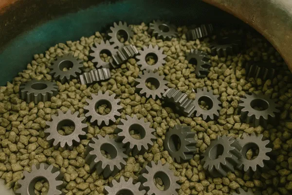
Dive deeper Paragraph: The surface of an as-sintered part has microscopic pores. For parts needing plating, this is a major problem. We learned this the hard way on a hydraulic component project years ago. Without sealing the pores, plating chemicals got trapped and caused corrosion. Now, for any part requiring plating or pressure-tightness, resin impregnation is standard. For other applications, a process like steam treating can economically improve hardness and wear resistance, as detailed in industry publications like Powder Metallurgy Review. For the tightest surfaces, we can also perform secondary CNC machining services to achieve finishes that PM alone cannot.
| Finishing Method | Primary Effect | Cost Impact | Typical Roughness (Ra) |
|---|---|---|---|
| Tumbling / Vibratory | Deburrs, smooths edges | Low | 32 µin |
| Steam Treating | Improves hardness, wear, corrosion | Low | ~40 µin |
| Resin Impregnation | Seals porosity for plating/pressure | Medium | N/A |
| Plating (Zinc, Nickel) | Superior corrosion resistance | High | < 32 µin |
| Grinding / Machining | Improves finish & tolerance | High | < 16 µin |
What Common Design Mistakes Should You Avoid in Powder Metallurgy?
Simple design mistakes can ruin a PM project. These errors lead to weak parts, tooling problems, and high costs. Knowing these common pitfalls will save you from major headaches.
Common mistakes include designing sharp internal corners[^17], which cause stress and cracking. Also, avoid thin walls or feather edges that are fragile and hard to fill with powder. Variations in cross-sectional thickness can also lead to inconsistent density and weak spots.
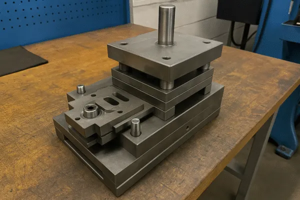
Dive deeper Paragraph: It’s a core principle of Design for Manufacturability (DFM) that saves our customers money. I always tell our engineers to "think like the powder." The metal powder has to flow into every corner of the die cavity evenly. Our engineering team reviews every new RFQ for these potential issues. This review saves our customers money and time before tooling is ever cut. For example, designing holes perpendicular to the pressing direction is a classic mistake we can often solve with a small design change, saving you thousands on tooling. It's this kind of partnership that builds long-term success.
| Mistake (Don't Do This) | Problem It Causes | Solution (Do This Instead) |
|---|---|---|
| Sharp Internal Corners | Stress concentration, tool wear | Add generous radii or fillets (>0.030") |
| Thin Walls (< 0.060") | Poor powder fill, weak & fragile parts | Increase wall thickness for robustness |
| Large Cross-Section Changes | Uneven density, warpage during sintering | Maintain uniform thickness or use smooth transitions |
| Side Holes / Undercuts | Requires complex tooling, cannot eject | Design all features parallel to pressing direction |
FAQs about Powder Metallurgy Design
How does the PM process compare to CNC machining? PM is ideal for high-volume production, offering low per-part cost and minimal material waste. CNC machining is better for low volumes, prototypes, and features that PM cannot mold directly.
What materials can be used in powder metallurgy? A wide range of materials are available, including iron-based alloys, stainless steels, copper alloys, and aluminum. The choice depends on your strength, corrosion, and cost requirements.
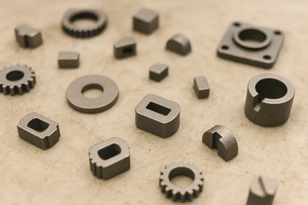
Is powder metallurgy suitable for large parts? PM is best for small to medium-sized parts. Part size is limited by the tonnage of our compaction presses. Most PM parts we produce weigh between a few grams and a few pounds.
Can threads be created directly in PM parts? Generally, no. Internal threads almost always require a secondary tapping operation. We handle this in-house to provide a finished part, but it's an extra step to account for in the cost.
What is the typical lead time for a new PM part? Lead time has two phases. First is tooling design and fabrication, which is typically 8-12 weeks. During this time we are providing PPAP documentation for your approval. Once approved, mass production is very fast.
Ready to Start Your Project?
Let my team's 30+ years of experience work for you. Send us your design files and we'll provide a free, no-obligation quote and a detailed Design for Manufacturability review.
Upload RFQ / Contact Prime Fabworks
Conclusion
Designing for powder metallurgy is straightforward when you focus on density, tolerances, finishes, and manufacturability[^4]. Use these expert guidelines to create strong, precise, and cost-effective parts for your next project.