
I chased the lowest quote. I paid with rework, late trucks, and lost customers. I changed how I buy and how I design, and my launches became calm.
Here is my short answer. Start with DFM before price. Lock strip layout, coil width, and grain direction so material yield reaches at least 85%. Prefer progressive dies unless a deep draw forces transfer. Put only functional GD&T and a clear burr limit on the print. Run SPC on CTQs with CpK ≥ 1.67. Follow APQP and PPAP when the market demands it. If you want a factory that already works this way, scan Prime Stamping Parts and send drawings via Contact so we can reply with a clean plan.
A cheap part can become the most expensive problem on your floor. I have lived through missed seasons and weekend firefights. I will not let that happen again. Below is what I put in RFQs, what I write on drawings, how I choose the die concept, and how I lock process control. You can copy this as your purchasing playbook today and send your first print through Contact when you are ready. If you prefer to see short examples first, skim my notes on the Blog and a few quick reads under Case Studies.
What Are Custom Metal Stamping Parts? A Complete Guide to Materials, Processes, and Uses?
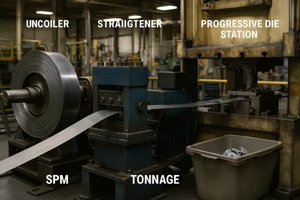
Many buyers think stamping is only cutting and bending. It is a system. If one link slips, cost and lead time explode. Custom metal stamping turns coil or sheet into precise shapes using dies in presses. Core steps include blanking, piercing, forming, flanging, coining, and sometimes in-die tapping or hardware insertion. With the right die concept, strip layout, and quality plan, coil becomes repeatable parts at speed and low landed cost. For a fast overview of what we cover, read Stamping Parts, check a few Case Studies, and then ask targeted questions through Contact.
The operations I lock in RFQs
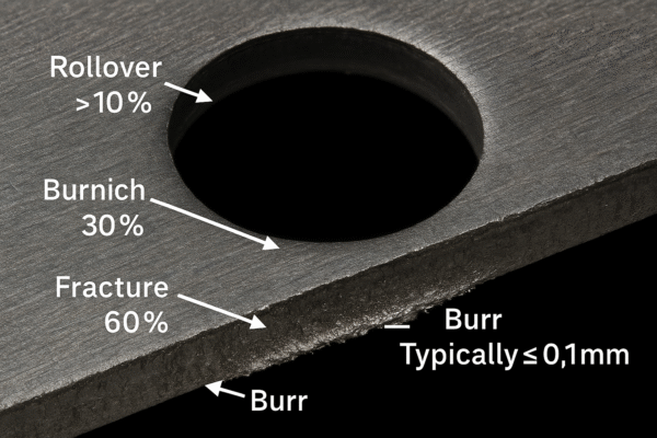
Blanking and piercing. I set die clearance as a percent of thickness. I start at 8% for low-carbon steel, 10% for stainless, and 12% for aluminum. If burrs rise, I tighten; if galling or tonnage spikes, I open slightly. I put these values in the RFQ so the first trial is not guesswork. I also define how we measure burrs inside the control plan; you can see how we lock that discipline under Quality Control
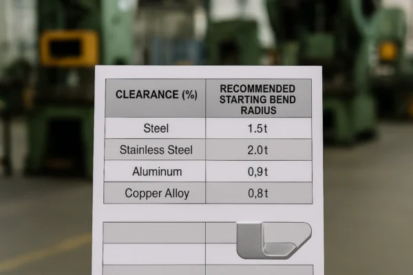
Forming and flanging. I set bend radii that match grade and temper. I try at least 1× thickness for mild steel, 1.5× for stainless, and 1× for aluminum. Small radii increase split risk and springback. If I need a crisp corner, I add a re-strike and confirm energy at the same SPM planned for mass production.
Coining and embossing. Coining sets precise steps and breaks sharp edges without a secondary deburr. It needs more tonnage and energy. I confirm press reserve at the stroke position we will use in production and verify again on the target press during run-at-rate.
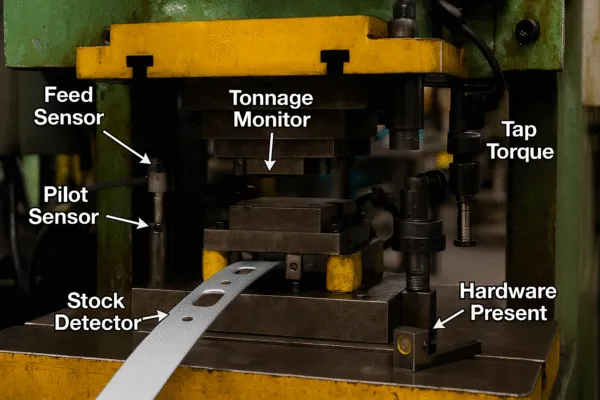
In-die tapping and insertion. When volume pays back, I add threads or clinch hardware in-die. I use presence sensors and tap-torque monitors and write those devices into the die-protection list. This cuts handling and reduces defects. It also makes PPAP data cleaner because checks become automatic.
Progressive vs transfer vs stage tools
Progressive die. One coil feeds through stations. One part drops every stroke. I default to progressive for small to medium parts with shallow to moderate forms. It gives high material yield and low labor. The consistent part attitude also simplifies packing into trays.
Transfer die. A transfer system moves parts between stations. I use it for deep draws and large shells. It runs slower and can increase material use. I switch only when geometry or risk demands it; if possible, I solve with a pre-form plus re-strike inside a progressive tool.
Stage tools. Useful for prototypes or tiny volumes. Labor is high and control is harder at speed, so I avoid stage tools for serial production.
Press tonnage and energy. I estimate blanking tonnage as perimeter × thickness × shear strength, then add forming tonnage and a safety margin. I do not stop at peak tonnage; I check press energy at the engagement point and at target SPM so the die does not starve. For automotive programs, I show this math in APQP gates and carry the same settings into PPAP; that matches the audit style shown in AIAG Core Tools.
Yield math. I freeze strip layout early. I set pitch, rotation, and carrier width. I align grain to protect bends and reduce splits. I test standard coil widths and compute yield: Yield % = (sum of part areas in one pitch) ÷ (strip pitch × coil width) × 100. If yield sits below 85% on a standard width, I redesign the layout before I talk price. In your RFQ, ask each supplier to show the strip image and the yield math; if anyone refuses, expect launch trouble.
Top Material Choices for Metal Stamping: Steel, Stainless Steel, Aluminum, and High-Strength Alloys?
Material drives most of the piece cost and most of the press behavior. I choose by stiffness per dollar, corrosion need, joining method, and supply risk. I then validate on the real press at speed. If you want to lock finish and masking early, I keep a short explainer under Surface Treatment; for a fast opinion specific to your drawing, send it through Contact.
Pick steel for cost and stiffness. Pick stainless for corrosion and heat. Pick aluminum for weight and conductivity. Match temper to bend radii and speed. Match lubricant to grade and SPM. Plan finish early so you do not create a paintline or solderability problem.
The material map I use
Low-carbon steel (SPCC/DC01). Elastic modulus about 210 GPa. Yield 140–280 MPa. Needs coating. Easy to form in annealed tempers. Lowest cost. Typical finishes: zinc, zinc-nickel, e-coat.
HSLA steel (340–590 MPa). Same modulus. Higher strength and more springback. Needs coating. Good when thin and strong beats thick and soft.
Stainless (304/301/430). Modulus near 190–200 GPa. Corrosion from fair (430) to excellent (304). 301 work-hardens and springs; I watch grain direction and coil hardness. I call out passivation when appearance or corrosion stability matters. For GD&T language, I align symbols to ASME Y14.5 so every team reads the same rulebook.
Aluminum (5052/6061). Modulus near 70 GPa. Good corrosion with anodize or paint. For forming I prefer O or T4, then age to final strength if needed. I control galling with a micro-lube that wipes or washes before paint or anodize; when the part touches electronics, I check cleanliness against the IPC training references we cite in work instructions.
Copper and brass (C110/C260). Modulus 110–130 GPa. Great conductivity. Many spring tempers. Often plated with tin, nickel, or silver. I coin contact lands flat to control resistance and protect edges so they do not cut packaging films.
AHSS (DP590–1180, martensitic). Very high strength with higher forming risk. Needs careful radii, draw beads, and re-strike. I use PM tool steels or carbide in wear stations and watch tonnage trends to trigger sharpening.
When I set capability targets and sampling plans, I use primary references so audits go faster: the NIST capability primer and the indices overview from ASQ.
Finishes and compliance. I choose finish to match the real environment. If a buyer says “salt spray,” I confirm the exact method and use ASTM B117 for context. If the part must be RoHS-compliant, I reference the European Commission page RoHS overview. When chemicals or registrations matter, I point to Understanding REACH. If safety marks or flammability ratings enter the RFQ, I align terms with UL Solutions from the start.
Design Optimization for Stamping: How to Cut Costs, Reduce Scrap, and Boost Efficiency?
Design is the cheapest lever. If the model ignores the strip, the press will collect the tax. I freeze strip layout, coil width, and grain direction before price. I target material yield above 85% on a standard coil width. I prefer progressive dies unless deep draw demands transfer. I use functional GD&T, true position, and a burr limit. I add in-die value where it pays back. I hold the plan with sensors and SPC. If you want a quick DFM review, send files through Contact and I will annotate both 2D and 3D.
My nine-step playbook
Strip layout first. I rotate the part until bends align with grain. I try to nest two or more cavities when press and feed allow it. I test standard coil widths like 300, 400, 500, and 600 mm (12, 16, 20, 24 in). I place pilots near the first hit after feed and before tight true-position features. I keep carriers stiff enough for in-die hardware and plan a clear scrap path so slugs do not ride back into punches.
Build cost into the print. I avoid blanket ±0.05 mm. I give true position on functional holes, flatness on datum faces, and perpendicularity where alignment matters. I set a burr limit such as ≤ 0.05 mm or ≤ 10% of thickness, tighter on sealing edges. I mark grain direction and define cosmetic zones and “no die witness” as needed. For symbol clarity, I point new team members to ASME Y14.5 so we speak one language.
Choose die type by physics. I start with progressive. I move to transfer only for deep draws, large side hits, or fragile nests. If a pre-form and a re-strike solve the geometry, progressive wins on yield and labor.
Set clearances and radii that work. I start clearance at 8% of thickness for mild steel, 10% for stainless, and 12% for aluminum, and tune during trials. I set bend radii per material and plan a re-strike for springy grades. I avoid zero-gap hems unless appearance demands it and the press has energy margin.
Add sensors and die protection. I specify short and long feed sensors, pilot-release checks, slug detection, tonnage by zone, tap-torque monitors, and hardware-presence sensors. I add a strip-end stop to save the tool. Small sensors save big money. For setup and maintenance safety, I align our wording to OSHA’s overview on hazardous energy OSHA LOTO overview and the detailed standard OSHA 1910.147.
Confirm press capacity and speed. I check peak tonnage and energy at engagement. I confirm bed size, shut height, feed window, and feed accuracy at target SPM. During APQP gates I record those numbers so PPAP shows the real settings; that matches auditors’ expectations per the format in AIAG Core Tools.
Plan heat treat, cleaning, and finish up front. If I need spring, I form soft and then harden, or I use 301 and let it work harden. If I plate high-strength steels, I add bake after plate to reduce hydrogen risk. I define passivation for stainless and anodize or powder for aluminum. I add masking drawings for threads and contact lands. We summarize finish choices in plain words under Surface Treatment.
Lock a quality plan that holds at speed. I define CTQs like hole true position, burr height, coin height, and flange angle. I require SPC with CpK ≥ 1.67 in mass production and run MSA on gages. I keep lot traceability back to coil heat. For capability terms I align teams with the NIST primer and the ASQ indices overview. For automotive files I use the language in AIAG Core Tools.
Package to protect, not just to ship. I use VCI for carbon steel on long ocean legs, ESD trays or shielding bags for electronics, and foam trays or paper interleaves for cosmetic faces. For drop and vibration I select the right ISTA method from ISTA Test Procedures and share the choice and pack photos in the launch deck.
Top Industry Applications: How Automotive, Electronics, and Consumer Products Use Stamped Parts?
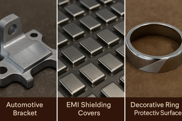
Each sector punishes a different mistake. Automotive punishes variation. Electronics punishes contamination. Consumer products punish cosmetics. I tune the same stamping logic to each world and I write the differences into the control plan so operators know what changes by job.
Automotive. I start with APQP and a real PFMEA. I select PPAP Level 3 for new programs unless the customer says otherwise. I perform MSA on gages before I collect SPC. I define CTQs and prove CpK ≥ 1.67 before I scale. I run at rate on the target press, feeder, oil, speed, and staffing. For system context I use IATF Global Oversight and align documents to AIAG Core Tools so sign-off is fast.
Electronics. I set tight burr limits and visible edge-quality checks. I pick micro-lubes that clean well and protect solderability. I plan a wash with ionic contamination limits and coin contact lands flat. I run ESD audits on the line and on the pack. For standards and training, I point engineers to IPC Standards and the course catalog at IPC Education.
Consumer products. I protect faces with PE film at the mill or in the die. I design quick-change inserts for logos and seasonal features. I write visual standards with photos and defect zones. I set carton drop tests and adjust stack height for long ocean legs. If you want to see how we package fragile finishes, message me through Contact and I will share tray sketches and label samples.
Two short case stories
Seat bracket that lost weight. A hard side form pushed the supplier toward transfer. I rotated the part and added a pre-form and a re-strike in a progressive die. I reached 88% yield on a 400 mm coil and held CpK 1.9 on true position. Launch went quiet, and warranty calls stayed quiet; I later wrote a short note on the Blog so new buyers see what changed the outcome.
Router EMI shield that kept cracking. The print bent 301 half-hard with the grain. It cracked at the corner. I changed grain, added a bead, and switched to a micro-lube with a wash. Solderability pass rose from 82% to 99.5%. When compliance questions came up, I aligned safety language with UL Solutions and kept finish choices consistent with IPC Standards.
FAQs: Straight Answers Buyers Ask Me Every Week
Q1. Why do cheap quotes become expensive on the press?
Because strip layout, grain, and press energy were not fixed in the quote. The die fights physics. Stops, rework, and scrap show up. I prevent this by locking DFM checks and requiring a strip image and yield math in every RFQ; if you want a starter checklist, ask through Contact.
Q2. How do I reach at least 85% material yield?
Lock coil width early. Rotate the part for tight nesting. Add cavities per pitch when press and feed support it. Remove excess webs. Compute yield for each width and pick the best standard width. Freeze it on the RFQ and the PO.
Q3. Progressive or transfer—how do I decide?
Start progressive. Move to transfer when deep draws, large shells, or fragile nests demand it. If a pre-form plus re-strike solves the geometry, progressive almost always wins on yield and labor.
Q4. What tolerances should I write on the print?
Use functional GD&T. True position for holes that locate fasteners or pins. Flatness on datum faces. Perpendicularity where alignment matters. Set a burr limit and mark grain direction. For symbol rules, I reference ASME Y14.5.
Q5. How do I estimate press tonnage quickly?
Blanking tonnage is perimeter × thickness × shear strength. Add forming tonnage and a safety margin. Check press energy at the die engagement point, not just peak tonnage. If you want us to check your part, send files via Contact.
Q6. What is the right die clearance?
Start at 8% of thickness for mild steel, 10% for stainless, and 12% for aluminum. Tune during trials. Watch burr height and tonnage. Adjust to control edge quality and tool life.
Q7. How do I control springback?
Use larger radii. Add a re-strike or coin. Choose softer tempers for forming. Set the die with slight over-bend. Use SPC on angle. Stainless and HSLA need more attention. For capability terms, I align teams with the NIST primer so charts match audit language.
Q8. When does in-die tapping make sense?
When volume is high, threads are M2–M6, and pitch time allows a full tap cycle at speed. Add torque monitors and lubrication control. This removes secondary operations and reduces handling defects.
Q9. What documents do I need for automotive PPAP?
DFMEA, PFMEA, control plan, process flow, MSA, capability studies, dimensional results, material certs, gage list, appearance approval when needed, and sample parts. Customers expect the format in AIAG Core Tools.
Q10. How do I keep solderability in electronics?
Use micro-lubes that clean well. Add a wash with ionic contamination limits. Coin contact lands. Control burrs. Pick finishes that support solder wetting. For standards and training, use IPC Standards and IPC Education.
Q11. What packaging stops rust on ocean legs?
Use VCI bags or paper, dry cartons, desiccant, and humidity cards. Control stack height. Avoid pallet crush. Use inner wraps on sharp edges. For testing, pick methods from ISTA Test Procedures to match your pack.
Q12. How do I set burr limits without killing cost?
Set a functional limit like ≤ 0.05 mm or ≤ 10% of thickness, tighter on sealing edges. Pair the limit with a clear measurement method. Use coining where hands touch or seals sit.
Q13. What CpK should I ask for?
For CTQs, I require CpK ≥ 1.67 in mass production. This gives room for drift. I also run MSA so I trust the numbers. A plain primer sits at ASQ.
Q14. What standards should I align to for safety and compliance?
For lockout/tagout I follow the OSHA LOTO overview and the detailed standard OSHA 1910.147. For RoHS I refer to the RoHS overview. For REACH I use Understanding REACH. For safety science and certification context I use UL Solutions.
Q15. How do I avoid missed seasons due to delays?
Freeze DFM early. Approve strip layout and yield. Confirm press and feeder. Book material with an alternate grade or width as backup. Plan PPAP data. Approve packaging with photos. Run at rate on the real line. If you want me to quarterback setup, send a calendar target through Contact.
Q16. Can I switch from transfer to progressive later?
Sometimes. If geometry allows, a re-tool can pay back fast with higher yield and speed. I test nesting and energy, then run a simple ROI. If it clears, I move; if not, I share the numbers so you see why.
Q17. What is the fastest way to cut piece cost by 10%?
Raise yield by 5–8 points with a better layout or coil width. Add another cavity per pitch if the press can take it. Move tapping in-die. Remove a secondary deburr with coining. If you want a focused plan for your drawing, send it via Contact.
Q18. Which references help me defend finish and pack choices?
Use ASTM B117 for salt spray context and pick drop/vibration methods from ISTA Test Procedures. For electronics cleanliness and solderability, cite IPC Standards so everyone speaks the same language.
Conclusion
Start with DFM and strip math. Choose the right die. Write functional tolerances. Add sensors and SPC. Plan finish and packing early. Then scale calmly. If you want me to review a part or build an RFQ with you, contact me through Contact after you skim a couple of examples on the Blog.