
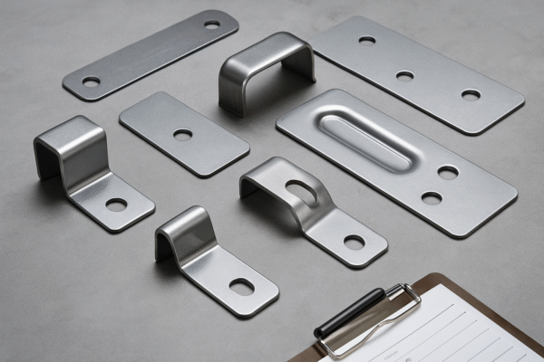
I see launches fail when parts drift, burrs grow, or cartons arrive crushed. I fix that with stable dies, clear data, and calm logistics that buyers can audit and engineers can trust.
Automotive teams choose custom metal stamping because a tuned die and a controlled line beat machining on repeatability and cost-per-piece. I hold ±0.05 mm on critical holes when the feature sits near pilots, keep burr under 0.05 mm with sharp tools and correct clearance, and prove stability with SPC that passes PPAP without drama.
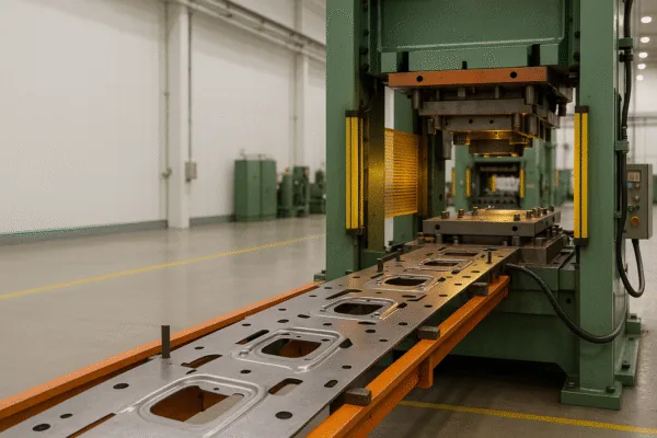
I write this from the floor and from the buyer’s desk. I speak in simple words. I show the numbers that move cost and dates. I spread anchors through this page so you can jump when you need proof or a quote. If you want to see typical brackets, terminals, and housings that we run every week, the anchor automotive metal stamping service opens samples, processes, and a scope you can source against.
Why do automotive manufacturers rely on stamped components?
I watch launches slip when variation climbs. I design dies and checks so every stroke repeats and every pallet traces to data. That keeps assembly calm and keeps sales off your back.
Stamped parts win because the die fixes geometry, the press fixes motion, and sensors catch mistakes before the parts reach the box. That gives predictable assembly time, fewer quality fires, and less overtime on Saturdays.
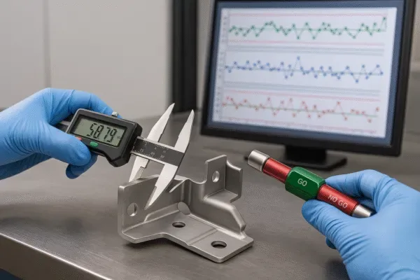
I set controls where the risk lives. I lock strip pitch with pilots that set a hard reference. I size punch-to-die clearance to the stock and the edge quality your assembly needs. I shape draw beads and set binder pressure windows to tame springback. I add misfeed, slug-detect, and part-ejection sensors that stop the press before steel bends the tool. I place vision at outfeed when presence/absence matters. I run SPC on features that affect fit and torque. I stop on trend, not only on hard fails, because trend is where loss begins. I publish Cp and Cpk for holes, angles, and flatness. I link every lot to coil heat, die hit count, and coat batch.
Control risks I put on day one:
| Risk you worry about | What I set up | How it protects you |
|---|---|---|
| Hole drift over time | Insert plan, wear map, regrind window | Stable holes for 1M+ hits before major service |
| Burr growth | Clearance, lube add-on, hit counter, SPC | Burr 0.05 mm sustained; auto-sort on alert |
| Springback | Draw beads and binder pressure windows | Parts seat without force or prying |
| Mixed parts | In-die sensors and outfeed vision | Line stops before bad parts reach pack |
| Missed launch | PPAP timeline and fallback capacity | Dates stay real; SOP holds steady |
Which materials and coatings should I choose?
Material can make a die sing or scream. I match grade, lube, radii, and coating to the target. I lock each input so the output stays steady. I confirm with coupons, not with wishful thinking.
I use HSLA 340/420 when I need strong, light brackets that still form without cracks. I use 6xxx aluminum when mass matters and paint-bake strength helps. I use 304/316 stainless in harsh zones where road spray or chemicals attack. I choose zinc-nickel when torque retention and long salt-spray hours matter. I choose e-coat when internal surfaces and edges need uniform film. I use phosphate as a base for paint or short transport. If your team needs a one-page primer on how aluminum behaves, the anchor “aluminum design properties” points to the association that maintains those basics at The Aluminum Association.
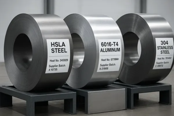
Material and coating snapshot:
| Material | Typical thickness (mm) | Strength (MPa) | Forming difficulty | Inside radius start | Tooling notes | Coating fit | Typical exposure |
|---|---|---|---|---|---|---|---|
| HSLA 340/420 | 1.2–2.5 | 340–600 | Medium | 1.0–1.5× t | Carbide pierce inserts; robust pilots | Zn-Ni, e-coat, phosphate | Brackets, mount tabs |
| 6016/6061-T4 | 0.9–2.0 | 150–250 | Med–High | 1.5–2.0× t | DLC/TiCN punches; polished radii | E-coat with Al pretreat | Shields, covers |
| 304/316 | 0.8–1.5 | 215–620 | High | 1.5–2.5× t | Staged pierce; high sharpness | Passivate; optional e-coat | Corrosive zones |
Coating chooser:
| Coating | Where I use it | Benefit | Watch-outs |
|---|---|---|---|
| Zinc-Nickel (8–12% Ni) | Steel in splash zones | Long salt-spray life; stable torque | Hydrogen control and post-bake |
| E-coat | Complex shapes; internal edges | Uniform film; edge coverage | Pretreat chemistry; drain design |
| Phosphate (Zn/Mn) | Pretreat or transport | Adhesion; short-term protection | Bath control; sludge removal |
Progressive die or transfer press — which fits my part?
I do not force a method on your part. I let geometry, volume, and risk pick the press. I move when the plan is clear and measurable.
Progressive dies win for small and medium parts with many pierces and light forms. Transfer presses win for deep cups, long flanges, and features that need more room than a strip can give. If you want pictures and real layouts, the anchor I shared near the top for automotive metal stamping service shows parts that live in progressive and housings that go to transfer.
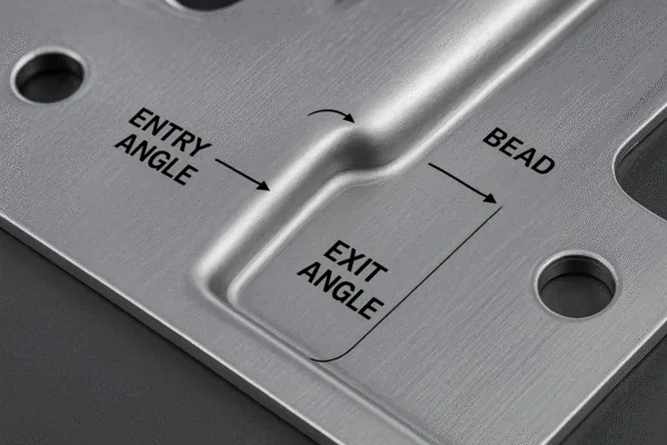
Side-by-side snapshot:
| Trait | Progressive die | Transfer press | Why |
|---|---|---|---|
| Small/medium, many pierces | ✅ | ❌ | Strip carries work; pilots lock location |
| Deep draw >2.0× t per stage | ⚠️ | ✅ | Larger stations; better flow control |
| Very large carrier | ❌ | ✅ | Fingers move blanks between wide beds |
| Million+ annual volume | ✅ | ⚠️ | Handling time adds cost on transfer |
| Fast debug and service | ✅ | ❌ | Compact layout; fewer moving parts |
Process flows:
| Step | Progressive die | Transfer press |
|---|---|---|
| Start | Coil feed, pilots, first pierces | Blank from coil or sheet |
| Middle | Pierce/form/emboss stations | Draw, redraw, pierce after stable form |
| End | Coin/restrike, cut-off, outfeed | Trim/flange/restrike, conveyor or robot outfeed |
What truly drives stamping cost?
Quotes look clean. Real cost hides in yield, uptime, and scrap. I show those drivers in the open at RFQ and keep them visible through launch.
Piece price rides on coil yield, uptime above 85%, scrap percent, tool amortization, SMED changeovers, energy, and the right press. I design strip layouts for yield. I build quick-service stations to protect uptime. I stop on trend before scrap piles up. I amortize tooling across real volume and ramps.
Cost levers and fixes:
| Driver | Metric | Target | Example fix |
|---|---|---|---|
| Yield | % coil into parts | +2% vs RFQ | Rotate nest; share webs; common punches |
| Uptime | % making good parts | ≥85% | Quick-change inserts; spare kits; sensors |
| Scrap | % rejects | ≤1.5% | SPC gates; lube checks; planned tool pulls |
| Amortization | $/part over life | Realistic | Phase tool payments with ramp |
| SMED | Minutes/changeover | 20 min | Quick clamps; pre-stage coils and tools |
| Energy | kWh/part | −10% | Right-size press; lube temp control |
How should I set tolerances and radii?
If the print fights physics, the die will punish your schedule. I help set the print so steel can make parts with less force and more repeatability.
I keep the tightest band on the hole that locates the mating part. I relax sibling holes that do not locate. I place pierces before heavy forms. I add restrikes where bend angles drive fit. I set inside radii at 1.0–1.5× thickness for steel, and larger for aluminum and stainless. I avoid sharp internal corners and tight edge distances.
Capability snapshot:
| Feature | Typical capability on a stable die | Notes |
|---|---|---|
| Hole diameter | ±0.05–0.08 mm | Control clearance and punch wear |
| Hole true position | 0.10–0.20 mm | Tie to pilots; avoid long carriers |
| Burr height | 0.05 mm | Sharp tools; right clearance |
| Bend angle | ±0.5–1.0° | Add restrike; manage springback |
| Flatness | 0.15–0.30 mm/100 mm | Leveling and controlled stack |
What lubricant and surface route should I choose?
Wrong lube breaks tools and ruins finish. Right lube keeps burr low and forms clean. I spec lube like a component, not like an afterthought.
For HSLA I run controlled-viscosity oil or dry film and keep add-on at 1–2 g/m². For 6xxx aluminum I fight galling with anti-gall synthetics at 2–4 g/m² and DLC/TiCN punch coatings. For 304/316 I use heavier EP oils at 3–5 g/m² and manage heat and wash. For e-coat routes I avoid silicone and confirm water-break and film thickness with coupons. If you want a quick, neutral overview of the e-coat bath science, the anchor “electrophoretic deposition” points to a clear summary at Electrophoretic deposition.
Lube and finish snapshot:
| Material | Lube type | Add-on (g/m²) | Tool coating | Post-wash surface |
|---|---|---|---|---|
| HSLA | Light paraffinic or dry film | 1–2 | TiN/Carbide on pierce | Clean; ready for Zn-Ni/phosphate |
| 6xxx Al | Anti-gall synthetic | 2–4 | DLC/TiCN | No stains; ready for Al pretreat + e-coat |
| 304/316 | Heavy EP oil | 3–5 | High polish; sharp edges | Clean; passivate; optional e-coat |
How do we pass PPAP fast and clean?
Paper does not cut steel, but it proves your parts are buildable every day. I keep the pack lean, true, and ready for audits.
I submit PPAP with Control Plan, PFMEA, MSA, dimensional and capability data, material certs, and PSW. I run Cpk ≥1.67 on critical features when the process is stable. I run GR&R before capability so bad gauges do not poison SPC. When your auditor wants the reference language, I point to the official oversight site at IATF 16949 global oversight.
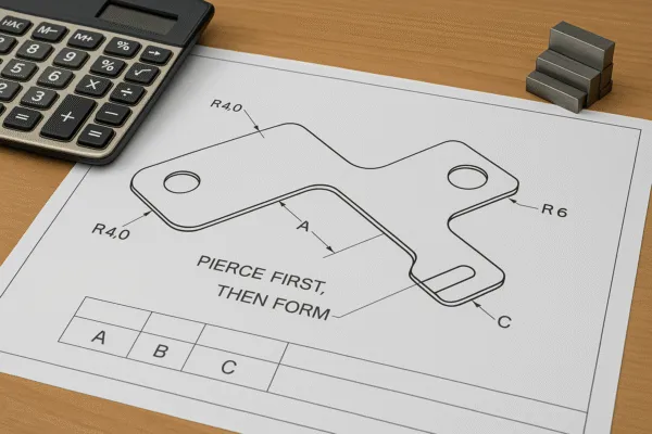
PPAP checklist:
| Doc | Status | Notes |
|---|---|---|
| Design records | Ready | Customer print + my DFM redlines |
| Process flow | Ready | Coil to pack with sensor gates |
| PFMEA | Ready | Updated after tryout |
| Control plan | Ready | Methods, gauges, frequencies, reactions |
| MSA (GR&R) | Ready | On hole size, angle, flatness |
| Dimensional results | Ready | 125-piece study with trace |
| Capability | Ready | Cpk ≥1.67 on criticals |
| Material certs | Ready | Heat numbers match labels |
| PSW | Ready | Signed after run-at-rate |
If your quality team prefers a familiar structure for training or cross-checks, I also echo the same outline used by the industry association at AIAG PPAP core tools.
What happens from RFQ to first shipment?
Speed without chaos comes from a simple plan and visible dates. I follow the same path every time, and I put it on one page so you can steer it.
RFQ and DFM produce a risk list and a quote. Award triggers die design and a strip or transfer layout. I build with standard parts and service points. Tryout logs hits, burr, angles, and hole sizes. I adjust beads, radii, and restrikes to stabilize. I coat sample parts and verify film. I pack to the trial spec and build the PPAP deck. Run-at-rate confirms cadence. We ship. When you want to start, the anchor upload RFQ lets you share prints, volumes, and target dates in one message.
Timeline snapshot:
| Phase | Output | Days (typical) |
|---|---|---|
| RFQ & DFM | Risk list, quote | 3–7 |
| Die design | 3D, strip/transfer layout | 7–21 |
| Build & bench | Tool ready for press | 21–45 |
| Tryout | First good parts | 3–7 |
| PPAP prep | Docs and capability | 5–10 |
| Run-at-rate | Approved volume run | 1–2 |
| First shipment | Packed, labeled pallets | 1 |
How do I keep parts safe in transit?
Good parts can die in bad boxes. I lock pack specs before PPAP so every trip is boring and clean. I match pack to finish and route.
I use double-wall cartons, custom corrugated or foam dunnage, edge guards, and stretch plus strap. I print 4×6 thermal labels on two sides and the top. I place VCI paper with Zn-Ni parts. I avoid chloride liners for stainless. I set pallet footprints to your racks and add barcodes that scan on your dock.
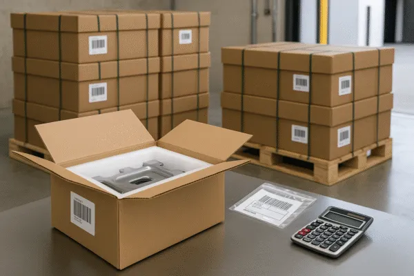
Packaging spec snapshot:
| Item | Spec | Why |
|---|---|---|
| Carton | Double-wall, 32 ECT+ | Crush resistance |
| Dunnage | Foam or custom cells | Edge and face protection |
| Pallet | 48×40 heat-treated | Export ready; consistent |
| Strap | Two PET straps | Load security |
| Label | 4×6 thermal, two sides + top | Scan from aisle |
| Moisture | VCI / desiccant as needed | Rust and spot control |
What makes dies last and stay quiet?
A quiet die makes a quiet launch. I choose tool steels and a service plan that keep noise low and output high.
I use PM tool steels and carbide where wear drives burr. I design inserts for fast swaps. I schedule regrinds by hit counts, not by hope. I stock spare punches and strippers. I color-code insert families. I log pulls with photos and tie them to lots so auditors get answers in seconds.
Tooling materials:
| Location | Material | Why | Notes |
|---|---|---|---|
| Pierce punches | PM M4 / Carbide | Edge life and stability | Add TiN/TiCN if lube is light |
| Dies/buttons | Carbide / A2 | Toughness vs wear | Match clearance to stock |
| Form inserts | D2 / DC53 | Polishes well; stable | Polish to reduce galling |
| Pilots | A2 + hard coat | Tough; serviceable | Keep spares staged |
How do you prevent crashes and mixed parts?
Crashes cost days and trust. I prevent them with simple sensors and clear reactions. I wire the risks, not the whole world.
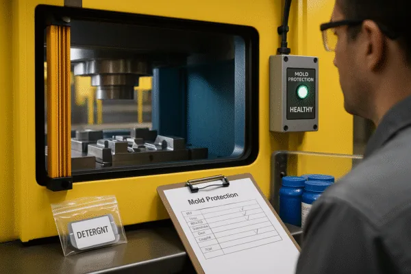
I add strip-end, misfeed, slug-detect, part-ejection, and pressure checks. I stop the press on fail. I verify each sensor at setup and at shift change. I train “stop, do not override.” I put vision at outfeed when presence/absence matters.
Common die protection:
| Risk | Sensor | Reaction |
|---|---|---|
| Misfeed | Pilot miss or feed-length switch | Stop before pierce hits wrong |
| Slug buildup | Inductive sensor near die button | Stop and clean die |
| Part not ejected | Photoeye at outfeed | Stop and clear |
| Low air/nitrogen | Pressure switch | Stop and check cylinders |
| Strip end | Prox or lever | Stop and change coil |
How do you keep the schedule honest?
I build a schedule that breathes. I show buffers and backups. I flag risk early. I give you plans A and B.
I blanket coil with cancel windows. I hold coating slots. I build spare inserts before SOP. I pre-approve a backup press. I book lanes that match dock hours. I hold a weekly review and publish a Gantt with red bars where risk is real. If a snag hits, we add a shift, open a second press, or run a short lot through a second path. When buyers ask for formal words, I align change-control and escalation to the wording your auditors know at IATF 16949 global oversight.
What should we watch for environment and compliance?
Clean audits come from clean habits. I keep oils, washes, and waste under control and traceable. I design parts to drain. I hang them so coat lines stay clean.
I avoid silicones on e-coat routes. I hold washer pH, conductivity, and temperature inside vendor ranges and record each check on a four-hour cadence. I clean sludge daily. I tie waste manifests to lots. I keep MSDS and lot records linked to each shipment. For a familiar PPAP outline that quality teams like to cross-check against, I mirror the structure in the association’s page at AIAG PPAP core tools.
FAQs — fast answers that match how buyers search
What tolerance can I hold on stamped holes?
±0.05 mm on stable progressive dies when holes sit near pilots and the strip is rigid. I control clearance, sharpness, and lube, and I add in-die checks on critical holes.
How do I keep burr below 0.05 mm on HSLA?
Run correct clearance, keep tools sharp, track hit counts, coin lightly if needed, and stop on trend. Verify with burr gauges or a stylus.
Progressive vs transfer — which is cheaper?
Progressive is cheaper for small/medium parts at volume. Transfer wins when deep draws or big carriers force big stations and careful handling. For comparison photos, use the anchor near the top for automotive metal stamping service.
What radii do I use for 6xxx aluminum?
Start at 1.5–2.0× thickness. Polish radii. Use coated punches. Plan overbend and restrike. Confirm with coupons before you freeze the print.
Is zinc-nickel better than plain zinc?
Yes for splash zones. Zn-Ni outlasts plain zinc in neutral salt spray and holds torque better. Manage hydrogen and bake. If you want lab language your buyer will accept, your auditor will point back to the industry’s salt-spray practice; I align our hours to that document when we set your test plan.
Can I e-coat stamped aluminum?
Yes with proper pretreat and drain design. Verify adhesion and film thickness. For an overview of the bath, the neutral anchor “electrophoretic deposition” maps to a clear primer at Electrophoretic deposition.
How do you meet PPAP?
I submit Control Plan, PFMEA, MSA, dimensional and capability data, material certs, and PSW. Run-at-rate closes it. The format preview sits under the anchor I placed earlier for PPAP documentation and quality plan.
What Cpk should I expect on criticals?
Cpk ≥1.67 when stable. ≥1.33 on secondary features if function allows. I share trends, not only snapshots.
How do you reduce scrap at startup?
Warm the die, seat the strip, gauge first-offs, adjust binder and beads, confirm lube add-on, and only then raise speed.
How long does a progressive die last?
With PM steels and a real service plan, over 1,000,000 hits before major regrind. I schedule by hit count, not by hope.
Do you tap in-die?
Yes when risk is low and lube is steady. Otherwise I post-tap or add hardware. I choose based on downtime risk and coating route.
Case stories — what changed when we fixed the basics
HSLA bracket with hole drift: Two holes were both ±0.05 mm though only one located the assembly. Burr rose and holes drifted after 220k hits. I reassigned location to the pilot-side hole, relaxed the other to ±0.10 mm, added a restrike, and set a wear limit. Cpk rose to 2.1; scrap fell 70%; launch pressure faded. I recorded the change and the reaction plan in our quality pack so the audit trail told a clean story; if you need a sample layout, you will find it via the anchor PPAP documentation and quality plan.
Aluminum shield with e-coat fisheyes: Lube carried into wash. Film broke. I changed lube, added a heated stage, set dry-off time, and drilled a drain in a blind rib. Film stabilized. Salt-spray hours passed against the test plan, and the customer closed the deviation and moved to full release.
Stainless clip with edge cracks: Inside radius was too tight; tool chipped. I increased IR to 1.8× t, polished, staged the bend, and raised lube add-on. Cracks vanished. Tool life improved. We added that note against similar parts in the service scope so buyers see it early through the anchor automotive metal stamping service.
What happens on the press — a simple walkthrough
- Coil loads on the uncoiler.
- Straightener flattens the strip.
- Servo feeder advances to pitch.
- Pilots lock position.
- Stations pierce, form, coin, and restrike.
- Sensors watch misfeeds and slugs.
- Cut-off releases the part.
- Vision or go/no-go checks fire.
- Parts stack and pack.
More quick tables — keep these handy
Bend radius and overbend:
| Material | Inside radius start | Overbend start |
|---|---|---|
| HSLA 340 | 1.0–1.5× t | 1–2° |
| 6016-T4 | 1.5–2.0× t | 2–3° |
| 304/316 | 1.5–2.5× t | 3–4° |
Press sizing hints:
| Parameter | Rule-of-thumb | Why |
|---|---|---|
| Peak tonnage | Add 20–30% headroom | Protects tool at draw |
| Bed size | Die length + 150–300 mm | Room for sensors and service |
| Energy | Tonnage over stroke | Avoids stall at form |
Tapped vs pierce-extrude holes:
| Method | Strength | Cost | Notes |
|---|---|---|---|
| Pierce-extrude + tap | High | Medium | Strong threads in thin stock |
| Nut insert | Highest | High | Best for serviceability |
| Plain tap | Medium | Low | Works if thickness allows |
Get ready for a quote — what I need from you
Send prints (2D/3D), annual volumes, target SOP date, coating spec and test hours, packaging and label rules, PPAP level, dock hours, and pain points from your current part. I will return a DFM note, a strip or transfer plan, a schedule, and a price tied to real drivers. When you are ready to start, the anchor upload RFQ lets you attach files and notes in one message so we can put dates on your calendar fast.
Conclusion
Stamped parts win when dies are stable, materials and coatings match the job, and cost drivers stay visible; send your print and I will build a calm launch you can trust. If you prefer to talk first, use the anchor you already saw near program steps: contact a stamping engineer.