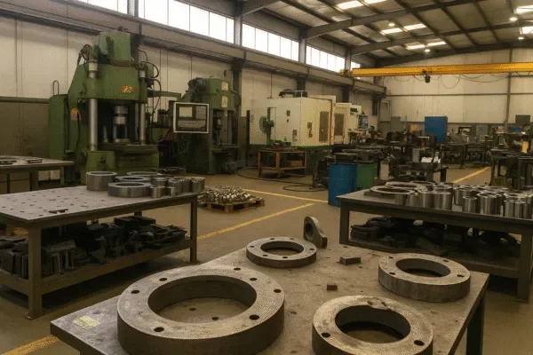
Choosing the wrong process for a critical part can lead to failure, budget overruns, and damage to your reputation. Imagine the cost of a product recall because a key component couldn't handle the stress it sees in the field. Understanding these core methods is the first step to making the right choice.
Forging creates the strongest parts by shaping metal with compressive forces, aligning its grain structure. Casting pours molten metal into a mold, ideal for complex shapes. Machining cuts a part from solid stock, offering the highest precision for prototypes and low-volume production. The optimal choice depends on balancing strength, cost, and design complexity.
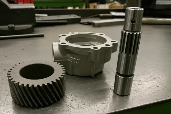
Choosing the right manufacturing process is one of the most critical decisions you will make. It impacts cost, strength, product lifespan, and safety. I've been navigating these choices for over 30 years and have seen firsthand how the right decision leads to success, while the wrong one causes expensive problems. We are not just a supplier; we are your partner in building a better, more robust product. Let's dive deep into the factors that matter from a seasoned buyer's perspective.
Which Process Creates the Strongest and Toughest Parts?
Your application demands a part that can withstand incredible, repeated stress without failing. A weak component is a liability. Let’s examine how each process affects the metal's internal structure and ultimate strength.
Forging produces the strongest parts due to its aligned, continuous grain flow, which provides superior resistance to fatigue and impact. Machining preserves the original strength of the bar stock but can create weak points by cutting through the grain flow. Casting results in a random grain structure, making it inherently less strong than forging.
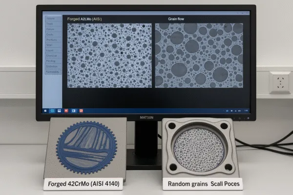
When we discuss strength, we're talking about the metal's internal grain structure. For instance, for high-strength, wear-resistant gears, using a forged 42CrMo (AISI 4140) alloy steel followed by quenching and tempering is a classic, reliable solution. The forging process forces the material's grain to follow the gear tooth's contour, drastically increasing its fatigue life. Casting, while excellent for complex shapes like a pump housing, has a random grain structure. Microscopic defects like porosity are a potential risk. For critical cast parts, we often use Non-Destructive Testing (NDT) methods like X-ray for internal voids or Penetrant Testing (PT) for surface cracks to guarantee internal integrity, a key step in our ISO 9001 certified quality process.
Beyond Grain Flow: The Role of Heat Treatment?
A part's final strength isn't just about the initial process; it's also about heat treatment. Forged parts respond exceptionally well to heat treatment due to their dense and uniform grain structure, allowing for deep and consistent hardening. This is critical for parts like axles and high-pressure valves. Castings can also be heat-treated, but the process must be carefully controlled to account for their internal structure, as rapid heating or cooling can sometimes cause distortion or cracking around areas of micro-porosity. Machined parts from pre-treated bar stock retain the properties of the raw material, but further heat treatment after aggressive machining may be needed to relieve internal stresses.
How Does Weldability and Assembly Factor In?
A single part is often just one piece of a larger assembly. Its ability to be welded is a critical design consideration. Due to their clean, uniform structure, forged parts are generally the most weldable, offering strong and reliable joints. Parts machined from solid bar stock are also highly weldable, as the base material is consistent. Castings, however, can be challenging. The material composition and potential for internal porosity can make welding unpredictable without specialized procedures and highly skilled technicians. If your design requires welding components together, the superior weldability of a forged part can simplify production and improve the final assembly's integrity. (For reference on structural welding requirements, see AWS D1.1/D1.1M.)
| Attribute | Forging | Casting | Machining from Solid |
|---|---|---|---|
| Response to Heat Treat | Excellent, Uniform | Good, Requires Control | Very Good (Material Dependent) |
| Weldability | Excellent | Fair to Good (Procedure Dependent) | Excellent |
How Do Costs and Tooling Investments Compare?
Your project budget is a primary factor, and high upfront tooling costs can be a deal-breaker. Choosing a process with expensive tooling for a small production run can destroy profitability. Let's break down the real costs.
Machining has the lowest tooling cost, making it ideal for prototypes and low volumes. Casting requires a moderate investment in molds. Forging demands the most expensive tooling (dies), making it financially viable only for high-volume production, where the per-piece cost becomes extremely low.
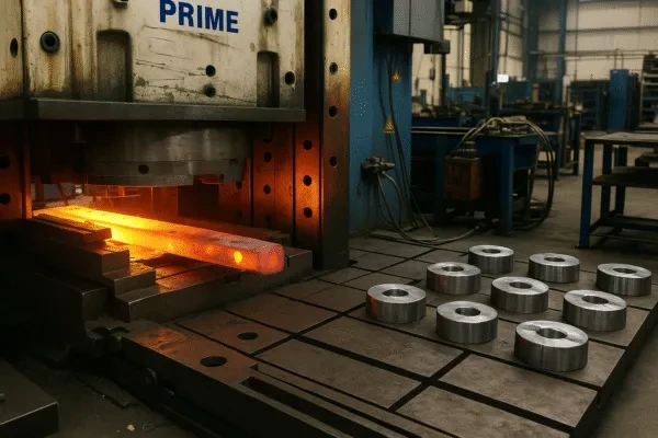
The cost structure for each process is completely different. It's crucial to look at the Total Cost of Ownership. A slightly cheaper cast part that fails in the field is infinitely more expensive than a properly specified component. To make this concrete, let's analyze a common part: a 100mm diameter gear made from 42CrMo (AISI 4140) alloy steel. Notice how the cost dynamics shift dramatically with volume.
Cost Analysis: 1,000 vs. 50,000 units (Example: 100mm 42CrMo Gear)
Not real price data,The actual price will vary depending on the specific product and manufacturing process.
| Cost Factor | Forging | Casting | Machining from Solid |
|---|---|---|---|
| Tooling Cost (Est.) | $25,000 | $8,000 | $200 (Fixtures) |
| Per-Piece @ 1k | ~$50.00 | ~$18.00 | ~$15.00 |
| Per-Piece @ 50k | ~$3.50 | ~$5.00 | ~$14.00 |
Hidden Costs: Where Do Projects Go Over Budget?
The per-piece price is only part of the story. Experienced buyers know to look for hidden costs. Forging and casting almost always require secondary costs like CNC machining for critical features, deburring, and surface treatments like shot blasting or painting. Machining a part from a solid block generates significant material scrap. While recyclable, you only recover a fraction of the raw material's initial cost. Furthermore, tooling isn't a one-time expense. Forging dies wear out and may need re-sinking or replacement after 50,000 to 100,000 cycles, depending on the material and complexity. Factoring these lifecycle costs into your initial analysis is key to an accurate budget.
Tooling Amortization and Ownership: What Should a Buyer Know?
When we quote a forging die, it's important to understand what you're buying. Typically, this is a one-time tooling charge that covers the engineering and manufacturing of the die set. While you pay for it, the physical tool often remains at our facility for maintenance and production. The key is to have a clear agreement on tool ownership and life. For our high-volume clients, we structure amortization plans where the tooling cost is spread over the first several production runs, lowering the initial cash outlay. We also provide transparent reports on tool life, so you can plan for refurbishment or replacement costs in advance, eliminating future surprises (see our approach to long-term support in After-Sales Care).
Which Process Offers the Most Design Freedom?
You have a complex design, but you're not sure which process can produce it effectively. Forcing a design into the wrong manufacturing method leads to quality compromises and higher costs.
Casting offers the highest design freedom, followed by machining, while forging is the most restrictive. Specifically:
- Casting: Can produce almost any complex shape, including internal cavities and hollow structures. Ideal for parts like pump bodies or manifolds.
- Machining: Very flexible for complex external profiles but is limited by the reach of the cutting tool for internal features.
- Forging: Best for solid, relatively simple shapes that must be designed with draft angles (tapers) for removal from the die.
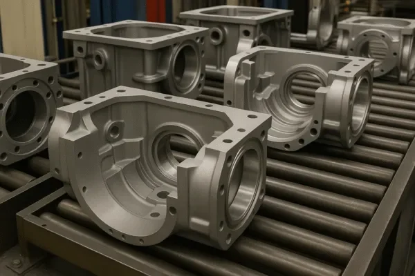
I remember a classic case with Kevin, a buyer from the U.S. sourcing a complex housing for Siemens. His team's initial plan was to machine 5,000 units. Our DFM (Design for Manufacturability) analysis showed this was not only expensive but slow. We proposed a switch to aluminum die casting. After a thorough PPAP validation, he approved the change. The result? We not only cut his per-piece cost by 60%, but we also increased the production rate from 500 pieces per week to over 2,000, helping him capture the peak sales season. That's the power of choosing the right process.
The DFM Process: A Deeper Look?
That success with Kevin was rooted in our DFM process. DFM isn't just about suggesting a different method; it's a collaborative engineering effort. Before we even cut steel for a die or mold, our engineers analyze your CAD model for manufacturability. For a casting, we look at wall thickness uniformity to prevent shrinkage defects. For a forging, we recommend optimal draft angles (typically 3-5 degrees) and generous radii to improve material flow and die life. For machined parts, we identify features that could be modified slightly to allow for more efficient tooling and faster cycle times. This proactive approach prevents costly design changes and production delays down the line. (If you want to see how we structure cross-process decisions, review our Innovative Matching Solutions workflow.)
Material Selection's Impact on Design Freedom
The material you choose is intrinsically linked to the process and design possibilities. You can't just pick a material and a process independently. For example, certain aluminum alloys in the 300-series family are designed specifically for the fluid flow and rapid solidification of die casting, allowing for incredibly intricate and thin-walled designs. Conversely, high-strength 7075 aluminum is best suited for forging due to its properties.
| Common Material | Best Suited Process(es) | Typical Application |
|---|---|---|
| Ductile Iron (65-45-12) | Sand Casting | Heavy-duty brackets, housings |
| A380 Aluminum | Die Casting | Complex electronics enclosures |
| 4140/4340 Alloy Steel | Forging | High-strength gears, crankshafts |
| 17-4PH Stainless Steel | Investment Casting, Machining | Aerospace, medical components |
| 6061-T6 Aluminum | Machining from Solid | Prototypes, structural plates |
(For deeper metallurgy references, see ASM International and materials databases such as ASM Matdata.)
The Art of the Trade-Off: When is 'Good Enough' the Best Choice?
A seasoned buyer knows that not every part needs the absolute best performance. Over-engineering a component can be just as costly as under-engineering it. The key is to find the optimal balance between performance and cost.
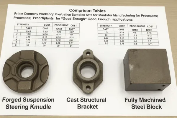
The best process is not always the strongest one; it's the one that meets or exceeds the application's requirements at the lowest total cost. A non-critical, low-stress part is often best made by casting or machining to save money, whereas a critical, high-stress part demands the reliability of forging.
Sometimes, the "good enough" solution is the smartest one. For a non-load-bearing bracket or a decorative cover, the supreme strength of forging is unnecessary and wasteful. Here, a sand casting provides more than enough strength at a fraction of the cost. The art of smart sourcing lies in this trade-off analysis. We see our role as helping you make these informed decisions, ensuring you don't pay for performance you don't need, while guaranteeing safety and reliability where it matters most.
A Practical Example: Choosing a Process for a Control Arm
Let's make this tangible with a common automotive part: a suspension control arm.
- Scenario A (High-Performance Race Car): Here, strength-to-weight ratio is everything. The choice is a forged aluminum alloy like 7075-T6. It provides the highest strength and fatigue resistance at the lowest possible weight. Cost is a secondary concern to performance and safety.
- Scenario B (Standard Passenger Car): For a vehicle produced in the millions, cost and reliability are key. The complex shape with multiple mounting points makes casting (often with ductile iron or cast aluminum) the ideal choice. It meets all safety standards and is incredibly cost-effective at high volumes.
- Scenario C (Prototype/Custom Build): When testing a new suspension geometry, you need a part fast and you might need to make changes. Machining from a solid block of 6061-T6 aluminum is the only logical option. It's the fastest way to get a functional part for testing without any tooling investment.
What About Tolerances and Surface Finish?
Your part needs to fit perfectly. The required dimensional accuracy and surface smoothness can dictate the manufacturing process or combination of processes.
Machining provides the highest precision with the tightest tolerances and best surface finish. Casting and forging have wider tolerances and rougher surfaces, almost always requiring secondary machining for critical mating features, bores, or surfaces.
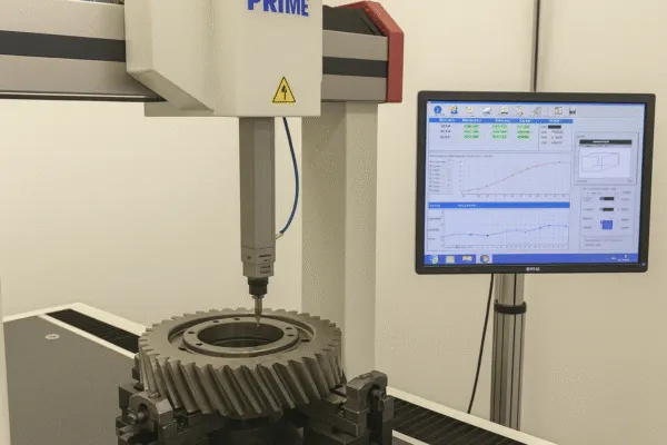
It's important to be specific. A sand casting might have a tolerance of ±1.5 mm, whereas precision investment casting (lost-wax) can achieve ±0.4 mm. Machining, by contrast, can easily hold ±0.05 mm. Often, a hybrid approach is best. We make a near-net-shape part using forging or casting to save on material and primary costs, then use our CNC machining services to finish only the critical surfaces (see our inspection approach in Quality Control).
Understanding Surface Finish Callouts (Ra)
When you see a surface finish callout like "1.6 Ra" on a drawing, it's specifying the average roughness of the surface in micrometers (μm). A lower Ra number means a smoother surface. A typical as-cast surface might be 12.5 Ra or rougher, which is fine for an external housing. But a surface that needs to seal with an O-ring will require a machined finish of 1.6 Ra or even 0.8 Ra to prevent leaks. Understanding these callouts helps you appreciate why secondary machining is often a necessary and value-added step. (Reference surface texture terminology and parameters in ISO 21920-2.)
Typical Tolerances & Surface Finish (Ra)
| Attribute | Forging (As-Forged) | Casting (Sand) | Casting (Investment) | Machining (Standard) |
|---|---|---|---|---|
| Tolerance | ±1.0 mm | ±1.5 mm | ±0.4 mm | ±0.05 mm |
| Surface Finish (μm Ra) | 12.5 | 12.5 | 3.2 - 6.3 | 1.6 |
(For dimensional tolerance systems for castings, see ISO 8062. For GD&T references, see ASME Y14.5 and ISO 1101. For general tolerances, see ISO 2768-1. For measurement science background, see NIST.)
How Does Lead Time Affect Your Project?
Getting your product to market quickly is a competitive advantage. The time from final design to physical part varies dramatically between these processes, especially for the first run.
Machining offers the fastest path to a first part, often in days, because no custom tooling is needed. Casting takes weeks due to mold creation. Forging has the longest lead time, often several months, because of the complex process of creating hardened steel dies.
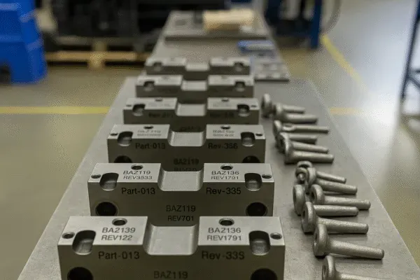
This lead-time difference requires strategic planning. I recall working with an agricultural client who needed to launch a new product for the spring season. We implemented a parallel-path strategy: we machined the first 100 parts for field testing while simultaneously starting the 12-week die manufacturing process. This "machine for speed, tool for volume" approach is one of our standard strategies to help clients capture market opportunities without delay. (If you’re planning prototype-to-production, start with this CNC Buyer’s Guide.)
Breaking Down the Lead Time: What Takes So Long?
To a buyer, a 12-week lead time for a forged part can seem long. Here’s a typical breakdown that demystifies the process and helps with project planning:
- Week 1-2: Final DFM review, simulation of material flow, and final sign-off on the forging drawing.
- Week 3-8: CNC machining of the hardened tool steel blocks to create the upper and lower die cavities. This is a slow, precise process.
- Week 9: Multi-stage heat treatment of the dies to achieve the required hardness and toughness, followed by final polishing or coating.
- Week 10-11: Die setup, press calibration, and production of First Article Inspection (FAI) samples.
- Week 12: Full dimensional and metallurgical inspection of FAI samples, submission of the PPAP report, and customer approval.
Understanding these steps helps clarify why quality tooling is a significant upfront investment in both time and money.
Get a Clear Path Forward for Your Project
Choosing the right process is a critical engineering and financial decision. We provide more than just a price. We provide a solution.
Trust Factors: ISO 9001 Certified | Serving 500+ Global Clients | 99.8% On-Time Delivery Rate
Ready for a quote and expert feedback?
→ Upload Your Drawing for a Free DFM Analysis & Quote Within 24 Hours
(Optional deep-dive references: forging ecosystem at the Forging Industry Association; casting resources via the American Foundry Society; die casting references via NADCA; quality management background via ISO Quality Management; and NDT personnel qualification reference via ISO 9712.)